Yamaha Sound xR Image Renderer System Identification
How does Sound xR Image translate spatial coordinates and rendering parameters into loudspeaker gains?
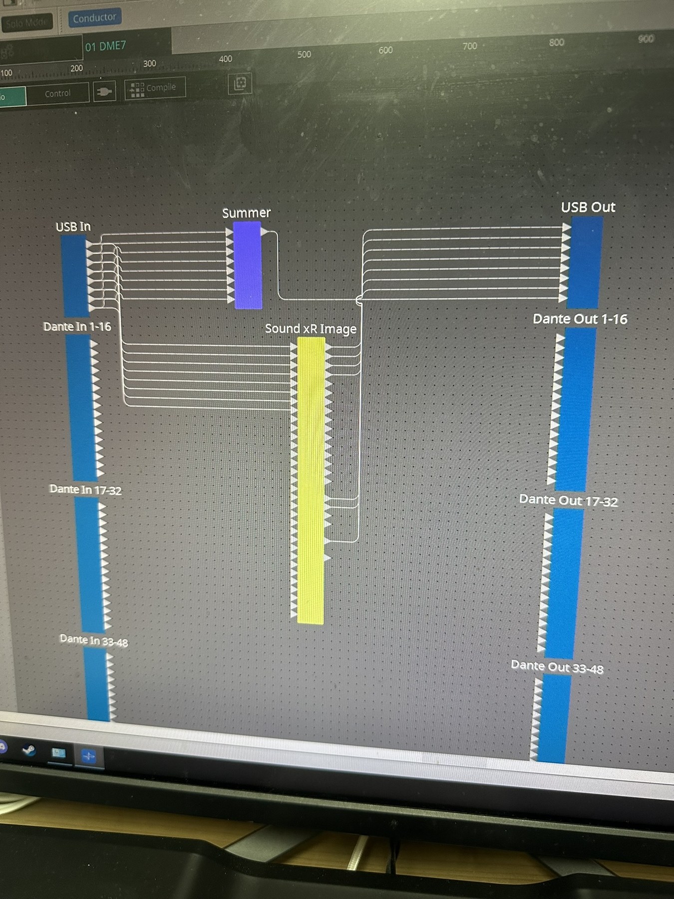
A Sound xR Image electrical measurement testbed paired with a numerical model-comparison workflow.
Vary loudspeaker coordinates and IDs, Object position, XY mode, Size, Precision, and Distance Attenuation while comparing recorded gains with candidate models.
In documented normal-output regions, inverse-distance weighting, five Precision settings, and constant-power normalization explained representative gain blocks to about 0.005 dB; ID-dependent and boundary behavior remain unresolved.
Verify channel mapping and state application, then test asymmetric positions, Object Z in XY OFF, small Size values, boundary transitions, and dynamic time response.
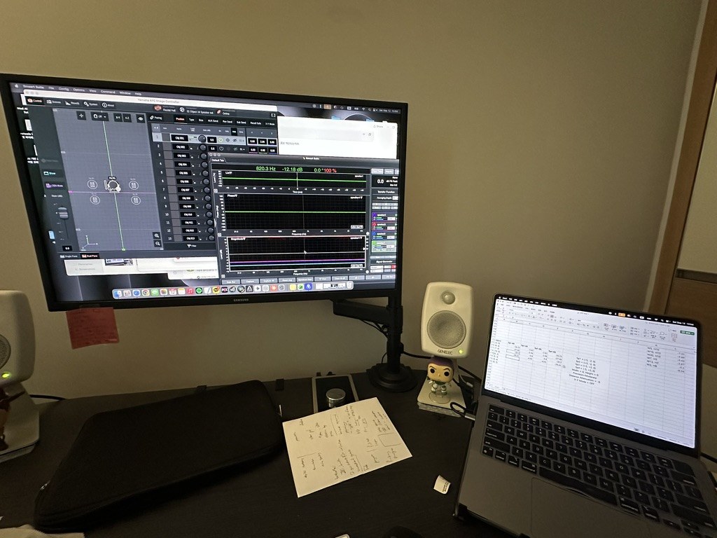
This study followed the outdoor Sound xR Image deployment and focused on the renderer itself. I treated the system as a black box, varying loudspeaker coordinates and IDs, Object position, XY mode, Width, Height, Precision, and Distance Attenuation while recording the resulting output gains.
The measurements were compared with numerical candidates while keeping observed values separate from inferred equations. The resulting formulas are bounded explanatory models, not claims about Yamaha’s disclosed internal implementation.
Within clearly documented normal-output regions, inverse-distance weighting followed by constant-power normalization explained the recorded gain distribution. The five Precision settings were consistent with distance exponents corresponding to approximately 8–12 dB of unnormalized attenuation per distance doubling, and representative verified blocks typically matched within about 0.005 dB.
Other behavior remains conditional. Size measurements support candidate effective-distance formulas only within the tested configurations, while boundary projection, Distance Attenuation, Object Z in 3D operation, and changes caused by loudspeaker-ID assignment do not yet reduce to one general rule. Repeated tests ruled out several simpler explanations, including a mere output-column swap.
The current outcome is a bounded renderer model suitable for a Max/MSP prototype, together with a prioritized validation plan. A fully compatible clone for arbitrary layouts, out-of-area positions, and dynamic motion requires further measurements of channel mapping, state application, 3D control paths, smoothing, and time response.